A voltage-controlled oscillator (VCO) is an electronic oscillator whose oscillation frequency is controlled by a voltage input. The applied input voltage determines the instantaneous oscillation frequency. Consequently, modulating signals applied to control input may cause frequency modulation (FM) or phase modulation (PM).
The Rapid Adoption Kit (RAK) referenced in this blog explains modeling VCOs in AMS Simulator (PSpice) using Analog Behavioral Model (ABM) parts. The following VCOs are discussed along with sample testcases:
- Sine Function VCO
- Dual Integrator VCO
- Controlled Reactance VCO
- Square Wave/Rectangle VCO
This post will be discussing sine function VCO, which can be either single phase or variable phase.
Single-Phase VCO (Simple VCO)
A simple form of VCO is obtained by starting with the time domain function for a sinusoidal source:
Sin((2*pi*fc*time)+phi)
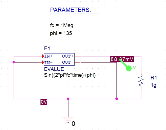
Fig 1 - Simple VCO
In this example, fc and phi are (constant) global parameters defined with a PARAM part. ‘2*pi’ is also a constant and PSpice recognizes ‘pi’. The above circuit is simulated for 10us (Run to time) with maximum step size of 50ns. The netlist for this circuit is:
E_E1 N00081 0 VALUE { Sin((2*pi*fc*time)+phi) }
R_R1 0 N00081 1g TC=0,0
.PARAM phi=135 fc=1meg
Output for this VCO is shown in Figure 2.
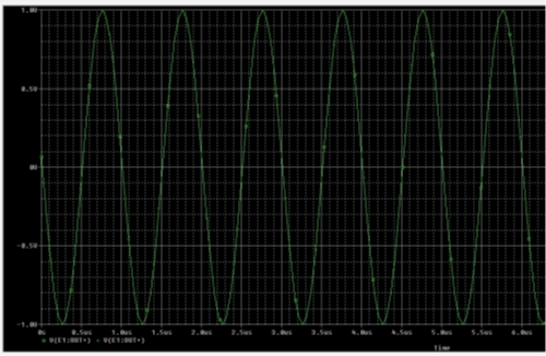
Fig 2 - Output of Simple VCO
Variable-Phase VCO
The single frequency source can be turned into a VCO by making phi a function of a controlling voltage instead of a constant: y(t) = sin(2*pi*fct + ɸ (t))
The instantaneous frequency is given by the time derivative of total phase: 2*pi*finst = 2*pi*fc + ɸ’(t)
The relationship between the frequency deviation, fd = finst – fc and ɸ is given by: ɸ(t) = ʃ2*pi*fd(t)dt
For a linear VCO we want fd to be proportional to the controlling voltage Vctrl , so: ɸ(t) = 2*pi*k1ʃVctrl(t)dt, where k1 is in Hertz/volt.
In our example, fc is 1meg and k1 is 1meg and it gives an output signal that is 1 MHz for the first 5µs and 2 MHz thereafter. We have defined value 2*pi as a parameter, ‘twopi’ in the PARAM part for this circuit. In PSpice, the integrator can be modeled as a controlled current source plus a capacitor. The varying phase term is added into the controlled voltage (sine) source. Figure 3 shows the circuit.
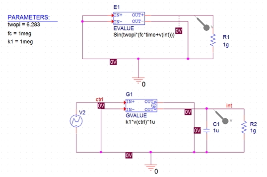
Fig 3 - Variable Phase VCO
The netlist for the circuit will be as follows:
E_E1 N00370 0 VALUE { Sin(twopi*(fc*time+v(int))) }
R_R1 0 N00370 1g TC=0,0
G_G1 0 INT VALUE { k1*v(ctrl)*1u }
C_C1 0 INT 1u IC=0 TC=0,0
.PARAM k1=1meg fc=1meg twopi=6.283
To complete the example, a controlling voltage is required. Here is a stimulus that starts at 0V, remains at this level for 5µs, then steps to 1V and stays there:
R_R2 0 INT 1g TC=0,0
V_V2 CTRL 0
+PWL 0 0 5u 0 5.01u 1
Output for this VCO is shown in Figure 4.
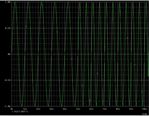
Fig 4 - Output of Variable Phase VCO
The detailed RAK along with the database is published at http://support.cadence.com/wps/mypoc/cos?uri=deeplinkmin:DocumentViewer;src=wp;q=ProductInformation/Silicon-Package-Board_Co-Design/RAK/PSpice/PSpice_VCO_RAK.pdf. You can refer to the RAK to know the methods used for the other types of VCOs discussed initially. Note: This RAK can only be accessed by Cadence customers who have valid login credentials for Cadence Online Support (http://support.cadence.com).
Naveen Konchada, Cadence Customer Support